
Building Description of G1 Camera Module Control Serial Port Protocol
Building Description of Camera Module Control Serial Port
The G1 camera module is a full-featured camera module combination developed by Huaxing Video based on the V39M chip of iCatch Technology, including the camera core motherboard,Camera module, a WIFI expansion board/network expansion board can be added according to the needs. G1 camera module, supports Uart serial port protocol, and can control G1 camera module to take photos and record videos through serial port.Here are the specific steps:
The driver needs to be installed on the computer for the first use.driveicatch_v3000_For_V37_V50_V35_V33_K33】
1. Connect Uart communication serial port
The G1 camera module has three combinations, and each combination can perform serial communication. According to different combinations, there are three ways to connect the communication serial port (users can freely match and use):
Method 1:Use the specifiedType-C serial portAdapter Plate(TYPE-C-ZJB V1.0), connected toG1 Camera MotherboardThen plug the cable on the serial port board into the correspondingtype-CAdapter PlateTX3、RX3、GNDLocation.
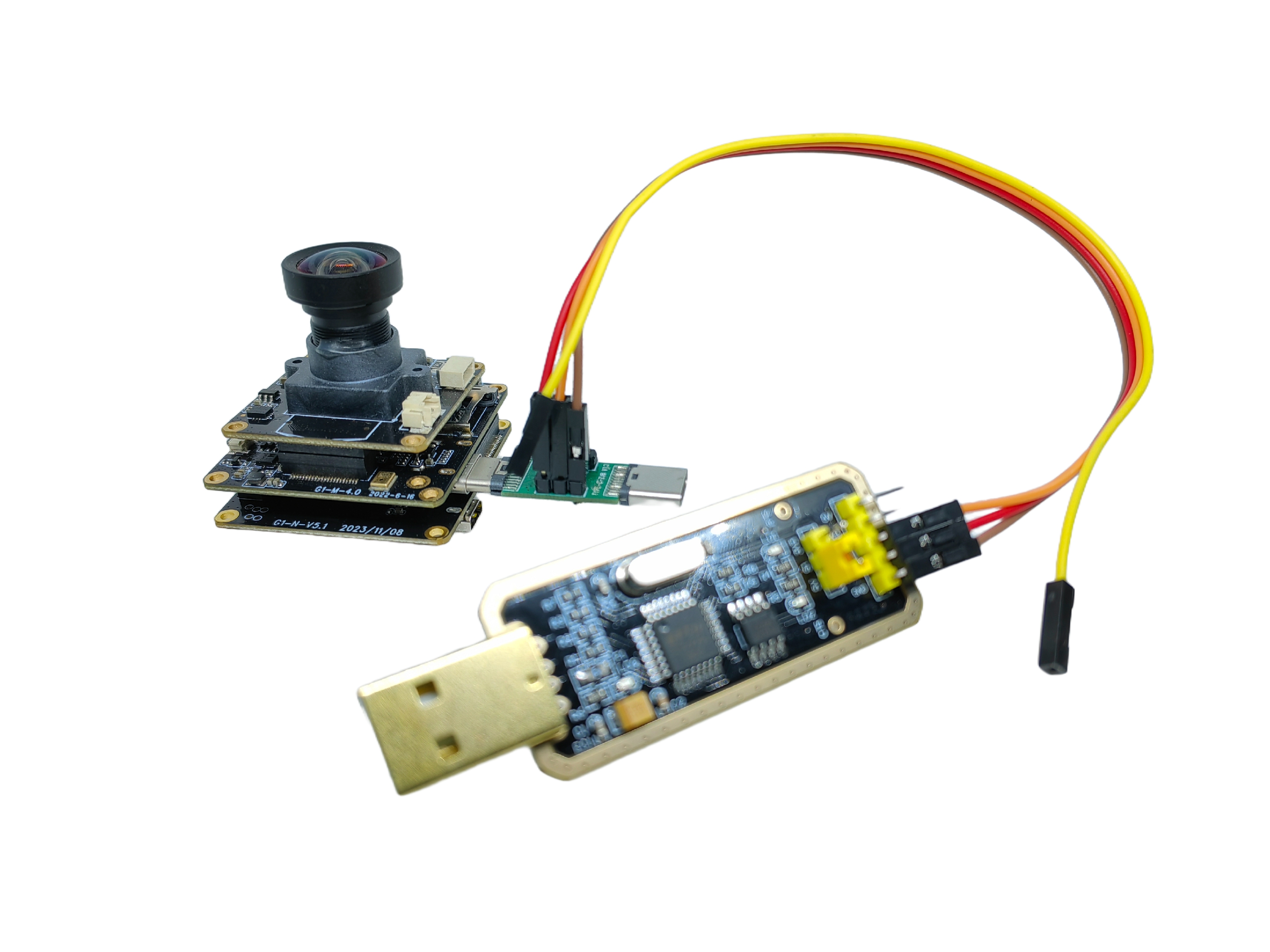
▲Type-C serial portAdapter board connection diagram
Method 2:WIFI boardThe "video and serial port" interface is expanded and reservedRX3、TX3,GNDThe camera can be set and controlled through this serial port.PThe single-end line with buckle is used as the extension line.
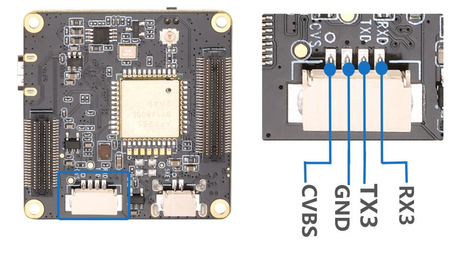
▲G1-W-V3.0 wifi board serial port interface definition
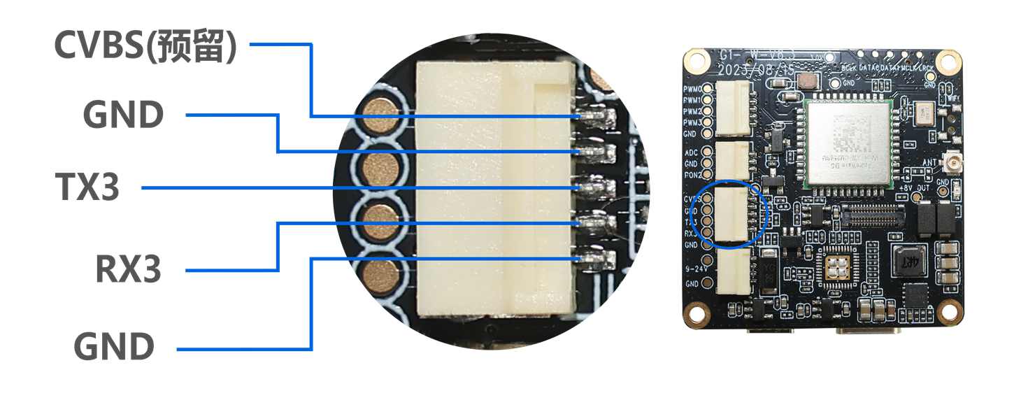
▲G1-W-V6.3 wifi board serial port interface definition
Method 3:Network port boardThe "serial port" interface is reservedRX3、TX3、GND,The camera can be set and controlled through this serial port。
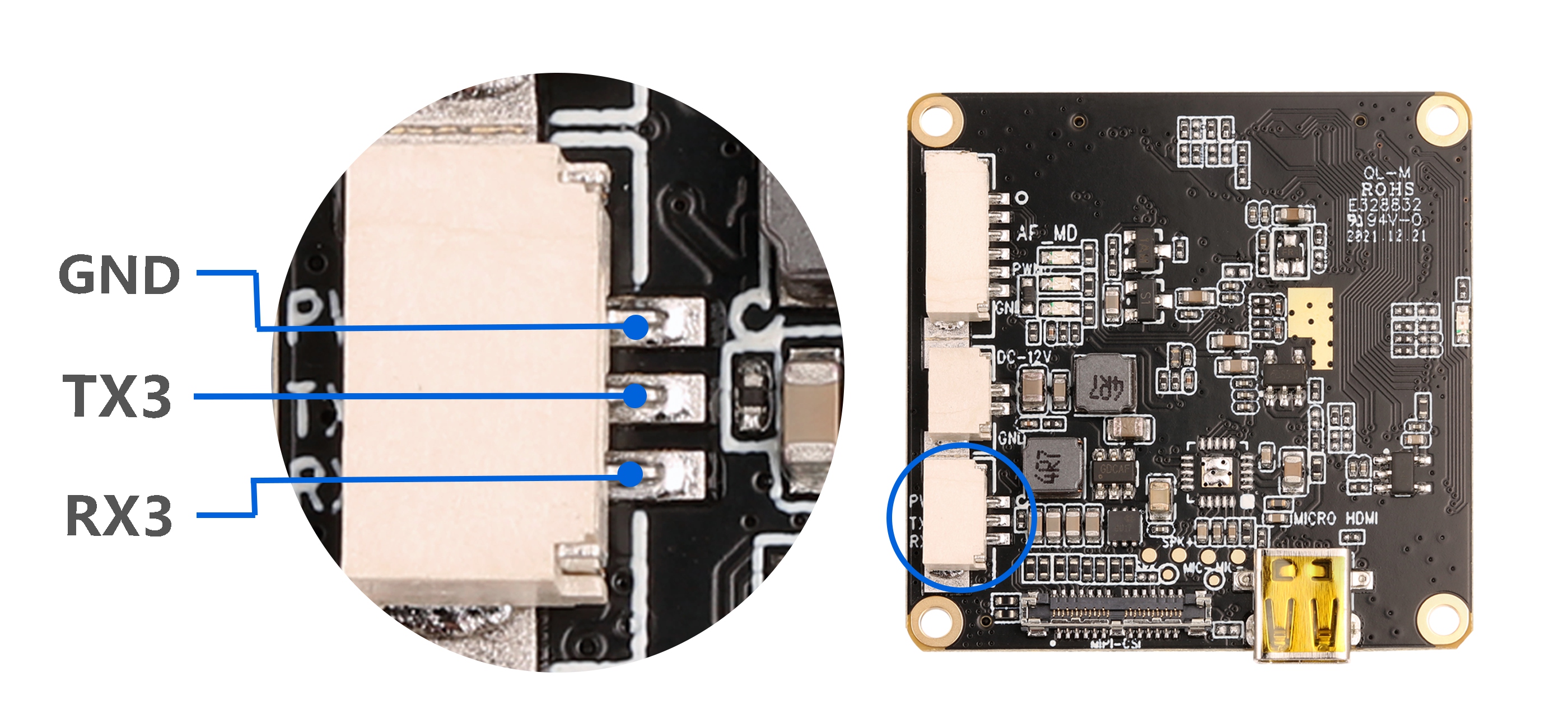
▲G1-N-V4.0 Ethernet board serial port interface definition

▲G1-N-V6.3 Ethernet board serial port interface definition
2. InstallationSerial protocol tool
Install the serial port protocol tool on the computer and click to download:XCOM V2.0.exe”;
3. The computer recognizes the serial port
Connect the serial port of the G1 camera module to the serial port board, connect the USB end of the serial port board to the computer, power on the G1 camera module, and you should be able to see the port read in the computer's "Computer" "Management" "Device Manager" such as:COM14, as shown below:

Note: If the G1 camera module is connectedUSBIf the serial port board is connected to the computer and the port is not found in the device management, you also need to install the USB to serial port driver【USB to Serial Driver】After the installation is complete, re-plug it.USBSerial port board.
4. Send serial port commands
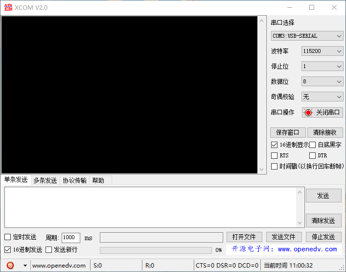
Open"XCOM V2.0.exe" tool, when the serial line is connected, select the option marked with a red box in the figure below, baud rate 115200, check hexadecimal display,Check Send in hexadecimal:
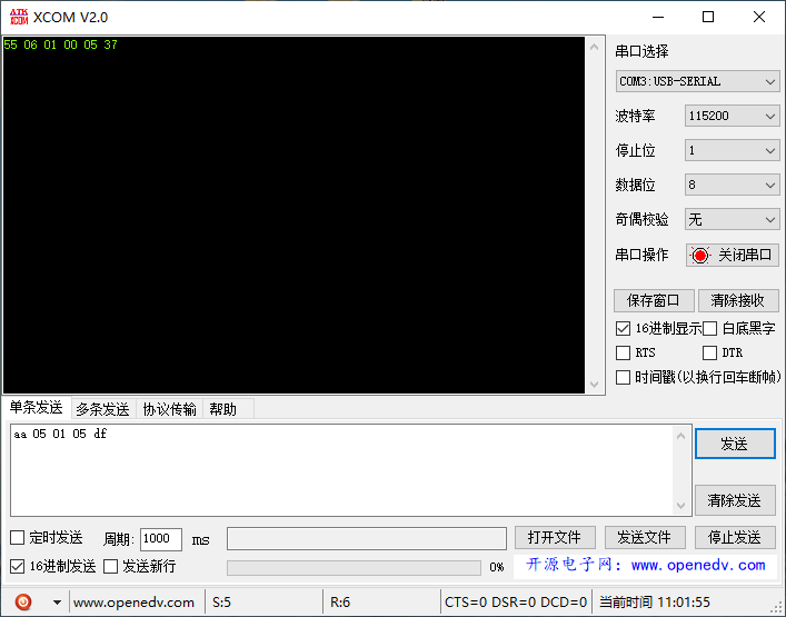
Enter the command in the command area of the window and click "Send". The G1 camera module will perform the corresponding action, such as: aa 05 01 05df Quick recording (start/stop recording regardless of the mode).
5. Serial port protocol commands
| Protocol Commands | Function | Return value (displayed in hexadecimal) |
| aa 05 00 01 2a | Get the camera version number | Display the return value according to the current version number of the camera |
| aa 05 00 02 80 | Get the protocol version number | Display the return value according to the current version number of the camera |
| aa 05 00 03 55 | Get the current camera working mode | Note: The return parameters will be different depending on the current mode, please see page 4 |
| aa 05 01 01 21 | Battery powered or adapter powered: switch modes (recording, taking photos, playback, main menu) Connect to computer: switch mode (USB disk, PCCAM) | 55 06 01 00 01 C9 |
| aa 05 01 02 8b | Take photo/record/stop recording in preview mode | 55 06 01 00 02 63 |
| aa 05 01 03 5e | Turn Wi-Fi on/off | 55 06 01 00 03 B6 |
| 05 01 04 0a | Quick photo shooting (take a photo regardless of the mode) | 55 06 01 00 04 AND2 |
| aa 05 01 05 df | Quick Recording (record/stop recording regardless of the mode) | 55 06 01 00 05 37 |
| aa 05 01 06 75 | format | 55 06 01 00 06 9D |
| aa 06 01 07 01 51 | Color Mode | 55 06 01 00 07 48 00 00 |
| aa 06 01 07 02 fb | Black and White Mode | 55 06 01 00 07 48 |
Note:wifiIn the state or network port state, the mode switching is not supported, that is, in this state, the input mode switching command is invalid.
Note: Connect to a computer to enterPCCAMAfter the mode is activated, the camera will exit if the quick recording command is used.PCCAMmode, and changes to the state of powering the device. In this case, if you needPCCAMTo preview the image, the camera needs to be re-pluggedUSBReconnect the computer cable and restart the machine.RecommendedPCCAMIn mode, useaa 05 01 02 8bRecording command.
Use Commandsaa05 00 03 55 Get the current mode status. The following table shows the corresponding return value in each mode. The return value is the current command word.(displayed in hexadecimal):
| state | Return value obtained by the serial port |
| Video Preview | 55 0F 00 00 55 73 62 20 50 43 4D 53 44 43 C4 |
| Photo preview | 55 0D 00 00 53 74 69 6C 6C 20 50 56 B7 |
| Playback Mode | 55 0C 00 00 50 42 20 4D 61 69 6E 29 |
| Setting Mode | 55 0E 00 00 4D 61 69 6E 20 4D 65 6E 75 A0 |
| Video shooting | 55 0E 00 00 56 69 64 65 6F 20 52 65 63 99 |
| Taking photo | 55 0D 00 00 53 74 69 6C 6C 20 50 56 B7 |
| OpenWiFi | 55 14 00 00 57 69 46 69 20 43 6F 6E 6E 65 63 74 69 6F 6E 8F |
PTZ serial port protocol commands:
Note: Only machines with PTZ can use the following PTZ commands to get corresponding responses.
| PTZ protocol commands | Function | Return Value |
| root 06 05 01 00 cd | Follow all | 55 06 05 00 00 6F |
| aa 06 05 01 01 18 | Heading follow, pitch lock | 55 06 05 00 00 6F |
| aa 06 05 01 02 b2 | Pitch and heading follow TF, gimbal follows | 55 06 05 00 00 6F |
| aa 06 05 01 03 67 | Lock Mode | 55 06 05 00 00 6F |
| aa 05 05 02 a7 | Back to center | 55 06 05 00 00 6F |
| aa 05 05 03 72 | Flip | 55 06 05 00 00 6F |
| aa 06 05 04 00 air | Sensitivity mode 0 (follow soft) | 55 06 05 00 00 6F |
| aa 06 05 04 01 3f | Sensitivity mode 1 (follow sensitivity) | 55 06 05 00 00 6F |