
G1-W-V6.3 WiFi Board (AW CM256SM) Wireless Wifi Expansion Board, Wifi Module
G1-W-V6.3 WiFi Connector(YES CM256SM)
1. Product Overview
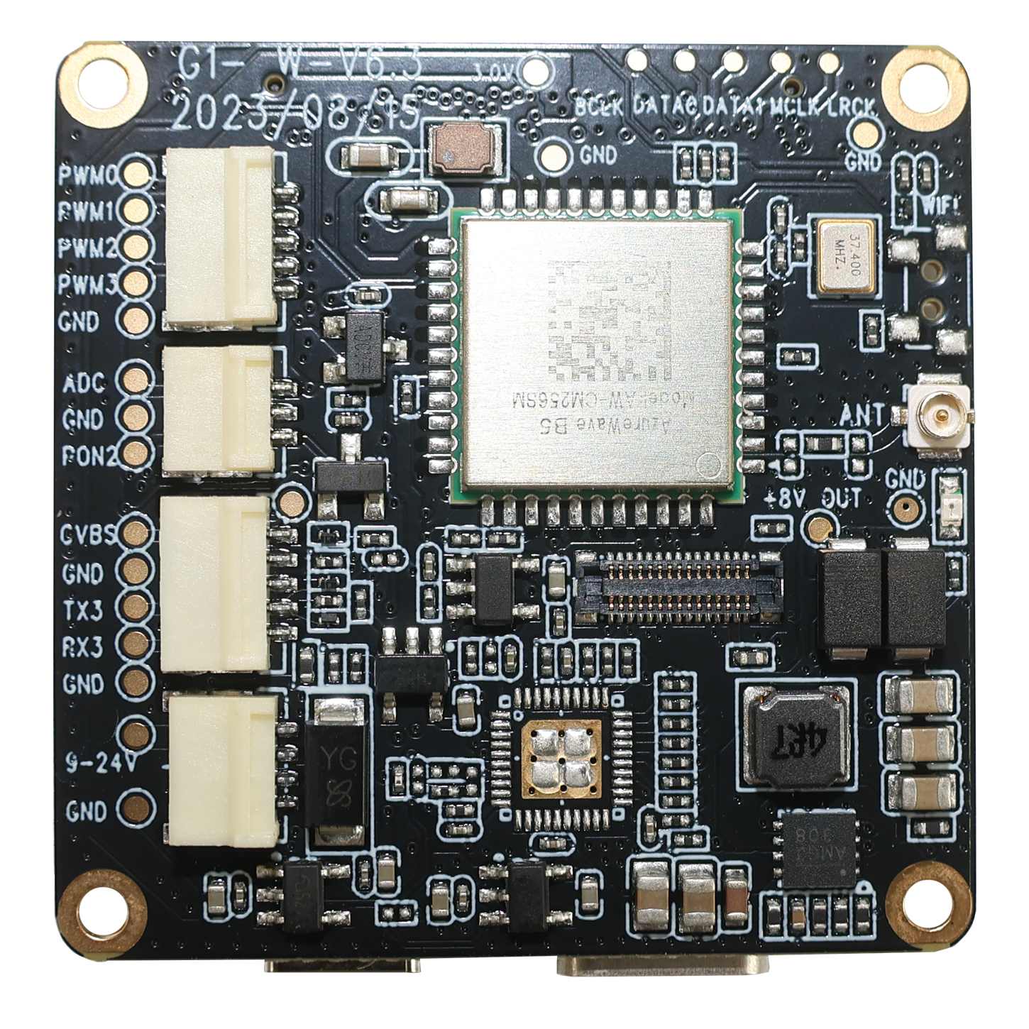
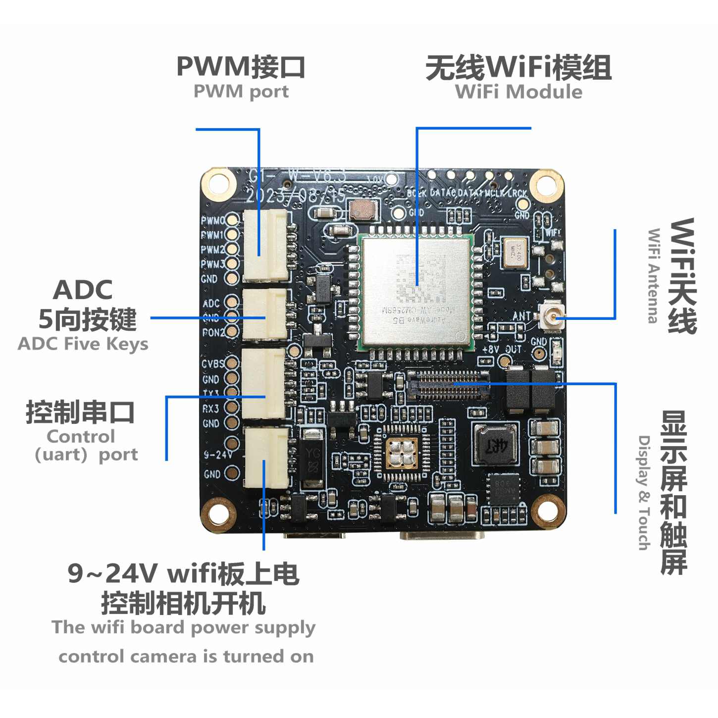
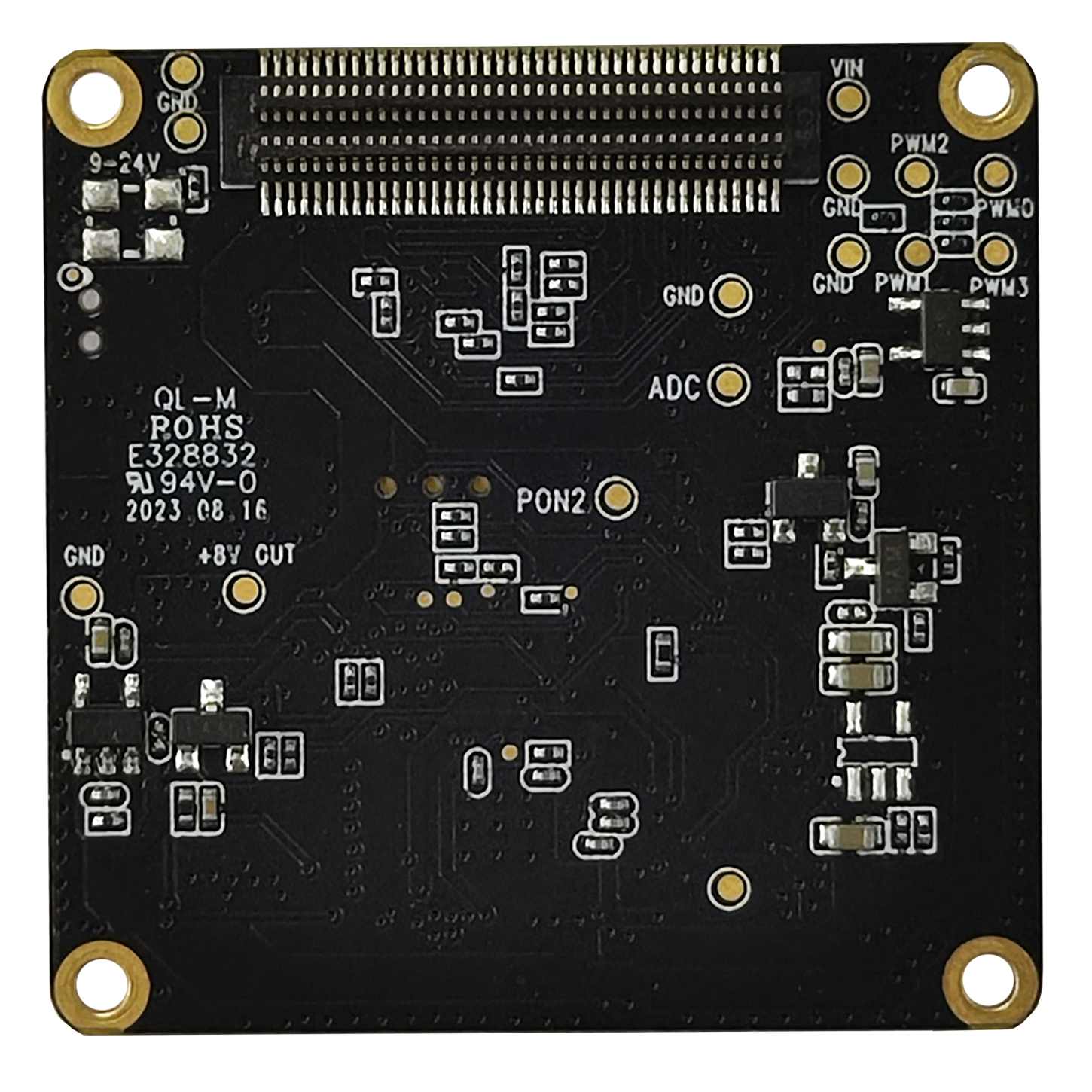
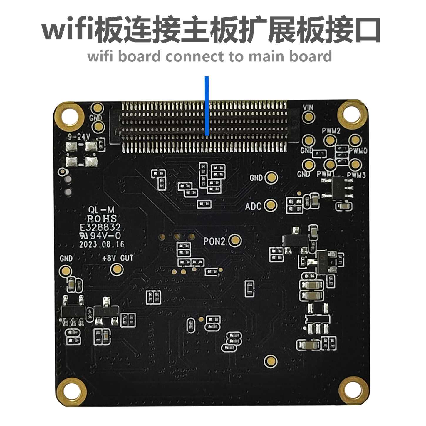
The G1-W-V6.3 WiFi board is equipped with the AW CM256SM single-pass dual-band WiFi module, supporting single-band 2.4G or 5G wireless WiFi functions. The board supports WiFi antenna, reserved WiFi button (C button), display, touch screen, reserved CVBS (TV-Out), serial port (Uart3), PWM, ADC button, power supply interface and other interfaces. The board frame size is 38*38mm and must be matched with the company's specifiedCamera motherboardThis product cannot work alone.
2. Specifications
| project | Parameter Description | project | Parameter Description |
| Product Name | G1-W-V6.3 PCBA(AW CM256SM) | Specifications | G1-W-V6.3 |
| Hardware version | G1-W-V6.3 | WifiModule | AW CM256SM |
Frequency band range RF Specification | 2.4G OR 5G | Wireless Network Standards WLAN Standard | IEEE 802.11b/g/n/ac, WiFi compliant |
| 2.4G frequency range Frequency Range | 2.400 GHz ~ 2.497 GHz (2.4 GHz ISM Band) | 5G frequency range Frequency Range | 4.900 GHz ~ 5.845 GHz (5.0 GHz ISM Band) |
2.4G channel Number of Channels | 2.4GHz:Ch1 ~ Ch14 | 5G channels Number of Channels | |
| 2.4G transmission rate | 2-3M Byte | 5G transmission speed | 6-8M Byte |
| 2.4G transmission distance | 50 meters (720P&1M in open space without interference) | 5G transmission distance | 30 meters (720P&1M in open space without interference) |
CVBS Standard (Reserved interface) | NTSC/PAL(TV-Out) | CVBS(TV-Out) (Reserved interface) | 720*576 |
| PWM | 3Pin PWM,1PIN APWMP | Serial port/Uart | RX3,TX3 |
| ADC button | Up, down, left, right, confirm 5-way ADC button,PowerPower button | ||
| Operating temperature | -10-+60°C | Storage temperature | -20-+80°C |
| humidityHumidity | 20%-80% | PCB size | 38*38MM |
| PCB screw hole spacing | 34MM | PCB screw hole diameter | 2MM |
3. Hardware interface function description
The AW CM256SM single-pass dual-band WiFi module supports single-band 2.4G or 5G wireless WiFi. It uses the first-generation IPEX universal copper standard antenna. (Press and hold the B button on the G1-V-6.3 motherboard for 3 seconds to turn on WiFi. The red light flashes when WiFi is on and stays on when connected.)
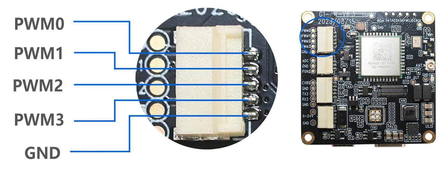
The above interface leads to the PWM function interface, which can be used to control camera mode switching, photo taking, video recording and other functions.
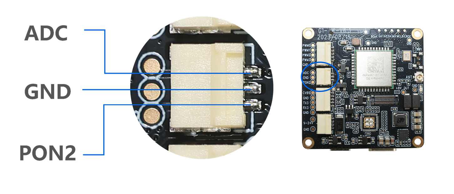
Supports one ADC button interface, which can be connected to five buttons: up, down, left, right, and confirm. It supports external buttons to control the camera's power on and off.
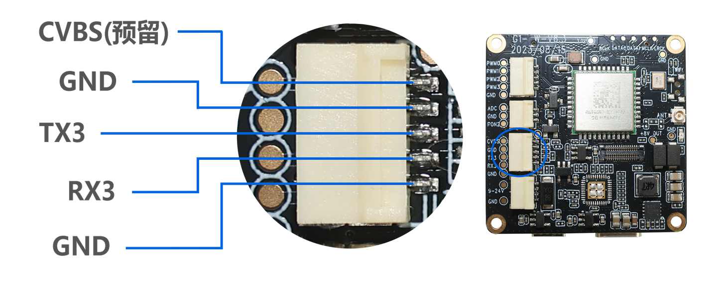
ReservedOne analog video CVBS (TV-OUT) signal output, customizable if required. Supports RX3 and TX3, allowing camera settings and control via this serial port.
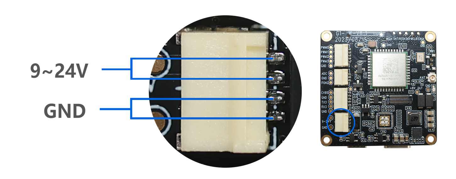
The camera can be powered automatically with a 9-24V power supply. The V6.3 hardware board supports three simultaneous power sources: the WiFi board, the mainboard battery, and the Type-C USB. A single power source is also supported.
Accessories list:
Yin and Yang hexagonal copper pillars M2*3.5+3 (5 PCS)
Steel pipe antenna (1PCS)
1.0mm pitch 3-pin single-ended cable with hook (1 PCS)
1.0mm pitch 4-pin single-ended cable with hook (1 PCS)
1.0mm pitch 5-pin single-ended cable with hook (2 PCS)
(Notice:Wire according to the specification, ignoring the wire color)
Assembly diagram:

▲(G1-M-V6.2 camera motherboard + IMX377Camera module+ G1-W-V6.3 Wi-Fi board)
Datasheet download:G1-W-V6.3 WiFi Board (AW CM256SM) Specification.pdf
Link to this article: http://www.wasintek.com/h-pd-83.html


