
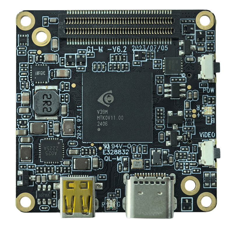
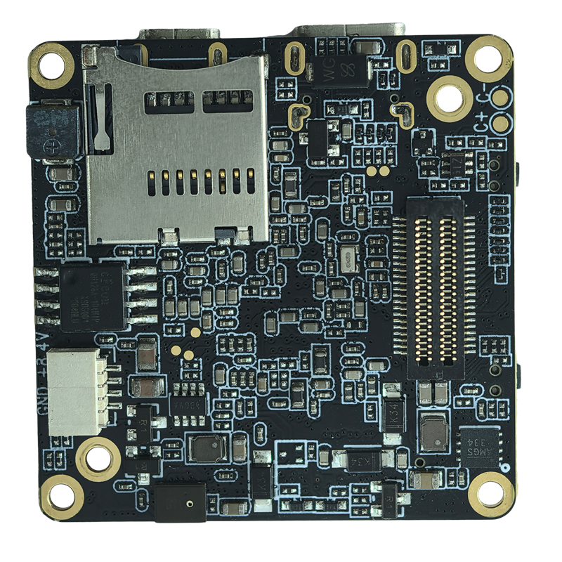
G1-M-V6.2 PCBA Camera Main Board (iCatch V39M) - The Core Main Board of the Camera
G1-M-V6.2 PCBA (V39M) Camerahostplate
1. Product Overview
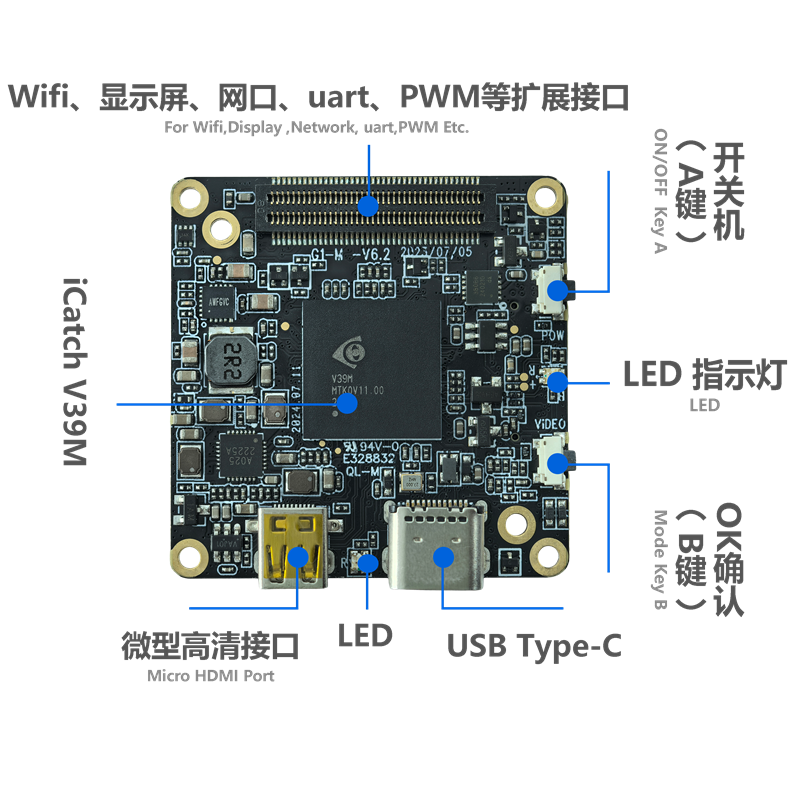
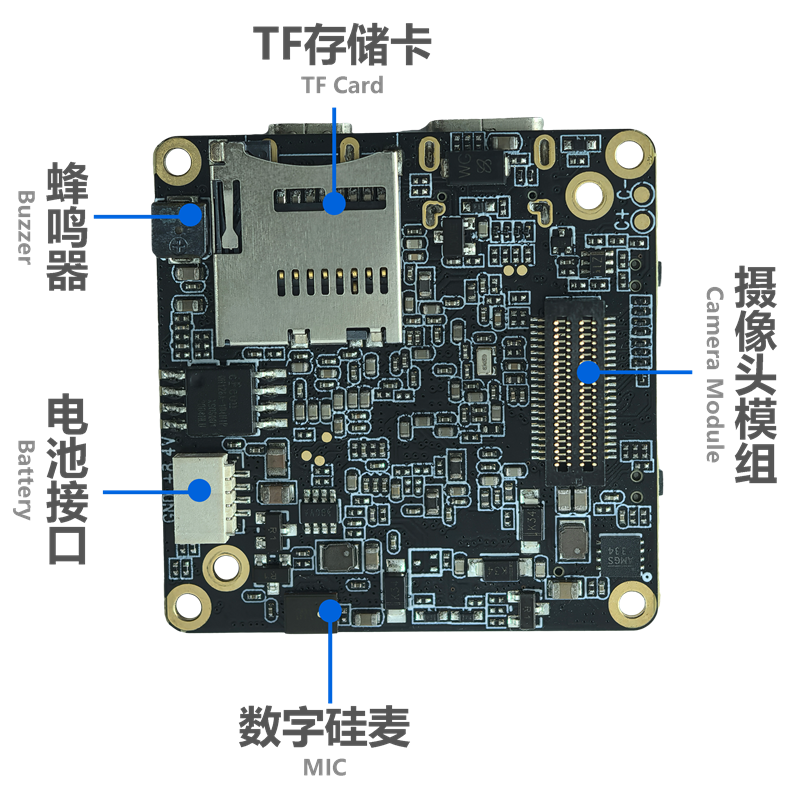
The G1 camera motherboard is equipped with the iCatch V39M camera chip and built-in 2GB DDR3. It supports up to 4K@60FPS (interpolated), 4K@30FPS, 2.7K@60FPS, and 1080P@120FPS H.264 encoded video. The board supports Type-C, HDMI, TF memory card, two control buttons, digital silicon microphone, buzzer, battery power supply, etc. It can support network port, Wi-Fi, display, CVBS, lens module, UART, I²C, SPI, PWM, MIC,DC power supply, ADC five-way buttonExpansion interface. The frame size is 38*38mm. Widely used in4K action camera, aerial photography drone camera, anti-shake gimbal camera,usb camera, wearable cameras, work recorders,Industrial inspection camerasAnd other video camera products.
2. Specifications
2.1 Hardware Specifications
| project | Parameter Description | project | Parameter Description |
| Product Name | G1-M-V6.2 PCBA (V39M) | Specifications | G1-M-V6.2 |
| Hardware version | G1-M-V6.2 | Main control chip (DSP) | iCatch V39M |
| Sensorinterface | MIPI | Battery voltage | 7.4-7.7V High-voltage lithium battery |
| Hardware version | ExternalTFCard, support8G~512G class 10 andThe above cards are recommendedU3 | Type-Cinterface | Type-C USB 5V;Connected to computerINDisk mode; connected to computerPCCAM(Camera) Mode |
| Indicator light type | Three-color light (red, green, blue) | Button type | Power button (A button), OK button (B button) |
| HDMIinterface | Micro HDMIInterface output, can support up to4K 30FPSVideo signal output | ||
| Operating temperature | -10-+60°C (excluding housing) | Storage temperature | -20-+80°C |
| humidityHumidity | 20%-80% | PCBsize | 38*38MM |
| PCBScrew hole spacing | outside(34MM*4), within (28MM*2indivual) | PCBScrew hole diameter | 2MM |
| SupportedImage sensor(Sensor) | ①Sony IMX377(12M) ②Sony IMX258(13M) ③Sony IMX317(8M) ④Sony IMX290 (2M) ⑤OV OS12D40(12M) ⑥Sony IMX577(12M) ⑦Sony IMX385(2M) ⑧Sony IMX335(5M) ⑨Sony IMX386(12M) ⑩Sony IMX378(12M) | ||
| Extension interface | Network port, Wifi,Display screen,CVBS, audioIC, lens module,Uart*3、I²C、SPI、PWM、MIC、DC power supply, ADC five-way buttonwait | ||
2.2 Basic software functional specifications
| project | Parameter Description |
| Video resolution | 4K、2.7K、1080P、720P |
| Video frame rate | 24fps 、25fps 、30fps 、48fps、50fps、60fps 、120fps、240fp |
| Photo resolution | 20M、13M、12M、10M、8M、5M、3M、2M |
| USBCamera resolution | H.264:4K@30FPS,1080P@60FPS/30FPS,720P@60FPS/30FPS |
MJPG:4K@30FPS,1080P@30FPS,720P@30FPS | |
| YUV:480P@30FPS | |
| HDMIOutput resolution | 4K@30FPS,1080P@60FPS/30FPS,720P@60FPS |
| Slow motion | close,4K2X、1080P4X、720P8X |
| Distortion Correction | Off, On |
| ICE | Off, On |
| Video file segmentation | Unlimited, 1 minute, 5 minutes |
| Pre-recording | Off, On (start recording from 5 seconds ago) |
| Loop recording | Off, On |
| Continuous Shooting | support |
| Snapshot | support |
| Recording start and stop function | support |
| Timestamp | Off, Date, Date and Time |
| Time-lapse photography | Off, 3 seconds, 5 seconds, 7 seconds |
| Time-lapse photo interval | Off, 3 seconds, 5 seconds, 10 seconds, 30 seconds, 1 minute |
| Time-lapse photo duration | Off, 5 minutes, 10 minutes, 15 minutes, 20 minutes, 30 minutes, 60 minutes, 2 hours, 3 hours, 5 hours |
| Video delay interval | Off, 1 sec, 2 sec, 3 sec, 4 sec, 5 sec, 6 sec, 7 sec, 8 sec, 10 sec, 13 sec, 15 sec, 20 sec, 25 sec, 30 sec, 40 sec, 60 sec |
| Time-lapse video duration | Unlimited, 5 minutes, 10 minutes, 20 minutes, 30 minutes, 1 hour, 2 hours, 3 hours, 5 hours |
| Automatic shutdown | Off, 1 minute, 5 minutes, 10 minutes, 15 minutes |
| Light source frequency | automatic,50Hz、60Hz |
| Key tone | switch |
| Display brightness | Low, Medium, High |
| Display Settings | Standard, full screen |
| language | Simplified Chinese, Traditional Chinese,English |
| format | support |
| Restore factory settings | support |
Note: The actual resolution depends on thesensorThe specifications may vary depending on the module. Please refer to the corresponding module specifications for details.
3. Hardware interface function description
USB Type-Cinterface:
This interface supportsUSBStandard5VPower input, can power the motherboard, battery (recommended 7.4-7.7VBattery) charging. Connect to computer to read directlyTFCard files, asINplateUse. It can also be used asPCCAM USBCamera use.USBA camera control serial port is reserved on the interfaceUART3Debug serial port with one cameraUART1(Serial port function can be matched withG1-USBSerial port debugging board).Connected to computerINDisk mode:insertTFCard,USBConnect the other end of the computer to the computer, and it will automatically enter the defaultINDisk mode.Connected to computerPCCAMmodel:insertTFCard,USBConnect the other end to the computer and enter theINDisk mode, short press A button to switch toPCCAMCamera mode. (Right-click the computer "Computer", click the left mouse button in the pop-up prompt box to enter "Manage", "Device Manager", and you can see the name of the camera recognized in "Image Device"Wasintek camera. Open the Camera tool"amcap.exe”, you can see the current device preview).To charge the battery:Using the power supplyadapter(recommend5V2A)Charge the battery,The red light is on during charging and the green light is on when fully charged.
This interface can be expanded to multipleMIPI Sensor,IR-CUTFunction,LEDFill light*2 groups, serial portUART2, battery power output, micro three-axis gimbal and other functions.
If a camera module only supports coaxial cable connection, a G1-S-ZJB-V1.0 adapter plate is required to convert it into a coaxial connector. This configuration allows for flexible assembly.
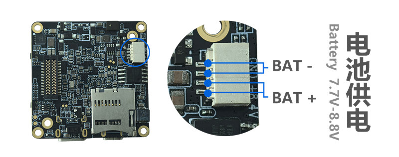
Battery powered:
6.8V(Low power shutdown)~8.4V, it is recommended to use 7.4-7.7VHigh voltage and high density battery.
Four,LEDLight indication:
Location | color | Power on | Video preview mode | When recording | Photo preview mode | Photograph | Playback Mode | Setup Mode |
Function indicator | red light | Constantly on | Constantly on | Flash | / | / | Red, green and blue are all on (white light) | / |
Green Light | / | / | / | Constantly on | Turn off | / | ||
| blue light | / | / | / | / | / | Constantly on |
Note: "/" means the indicator light is off
Note: When the device is powered on without a card inserted, the function indicator light flashes yellow.
5. Instructions for using buttons:
| category | Mode or state | Function |
| Power button/Mode button(Akey) | Power on/off | Press and hold for 1 second to turn on or off |
| Standby | Short press to switch modes, i.e., switch between video recording/photography/playback/settings; | |
| Settings (touch screen required) | Short press to scroll down the menu (after pressing the confirmation key (B key) to enter the setting item); Note: Use with the five-way button to scroll up the menu; | |
| Recording | Short press to pause and resume recording | |
| Confirm button/shoot button(Bkey) | Standby | In the video mode standby state, long press 3S to turn on/off the WIFI mode, the default is off (Needs to be used with a Wi-Fi board) In video mode, short press to start recording;In photo mode, short press to take a photo; Long press to start continuous shooting, release to stop continuous shooting; |
| Recording | Short press to stop recording and save the file; Press and hold for 2 seconds (less than 4 seconds) to take a single frame photo (release to execute); Long press (after 5 seconds) to continuously capture and take photos, release to stop capturing and taking photos; | |
Setup Mode (Requires touch screen) | Short press to confirm entry; Press and hold for 2 seconds to return; Double-click to switch modules: Photo Settings / Video Settings / System Settings / Gimbal Settings (only supported in the 3-axis gimbal version); | |
Playback Mode (Requires touch screen) | Short press to scroll up (previous file); Note: When connected to the WIFI expansion board, use it with the five-way button to achieve (next file); When playing a video or audio file, double-click to play/stop; Three clicks to mark as like or unlike; Mark like, that is, lock the file and do not delete it; Long press to enter the prompt option to delete the current file (long press to delete/short press to return), long press again to delete after entering, short press to return to exit the option. | |
| Shutdown | Press and hold the USB to enter the burning mode | |
| Reset function | Standby or working | Press the power button and the camera button at the same time to shut down the device. |
Note: When the screen is not in use, you can modify the setting parameters through the configuration file.CameraConfig_G1A.ini” (The specific configuration file name will vary depending on the lens module)TFIn the card root directory, you can modify the corresponding function options in the configuration file. Please save after modification. The modified parameters need to be turned on and off, and then turned on again for them to take effect.
Assembly diagram:
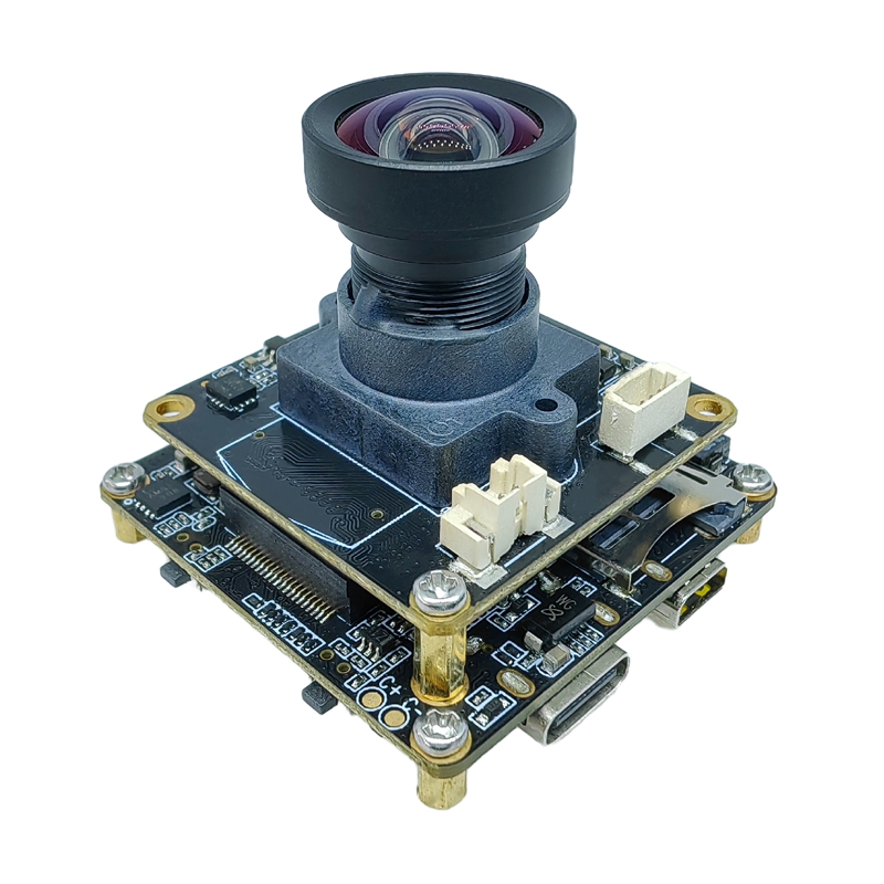
▲(G1-M-V6.2 camera motherboard + IMX377 camera module)
Datasheet download:G1-M-V6.2 PCBA (V39M) Motherboard Specification.pdf
Link to this article: https://www.wasintek.com/en/h-pd-203.html


